Sensor Introduction
The ACS37220 is a high-power density current sensor from Allegro Microsystems, designed to support galvanically isolated Differential Hall-Effect current sensing. It delivers robust and precise measurement performance with integrated fault detection and fast response, suitable for high-current and safety-critical applications.
This 5V sensor, offered in Allegro’s compact EZ™ 4×4 mm QFN Package, supports bidirectional current sensing up to ±200A. With factory calibration ensuring ±1.8% sensitivity error and a rapid fault current response time of 3μs, the ACS37220 stands out for both accuracy and speed.
The sensor outputs a ratiometric analog voltage proportional to the sensed current, and includes a digital fault output pin that activates on overcurrent conditions.
It is AEC-Q100 Grade 0 automotive qualified for operation from –40°C to +150°C.
Demo Board Overview
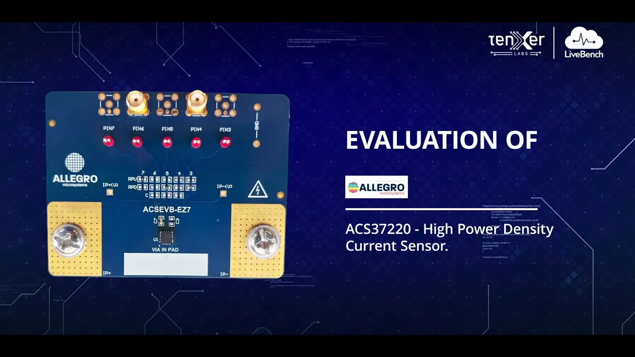
The ACSEVB-EZ7 evaluation board integrates the ACS37220 EZ-packaged sensor and provides a streamlined interface for injecting and measuring high current. The board includes screw terminals for ±200A current input, SMA/test headers for probing the analog and fault outputs. Designed for flexible test setups, the board includes configurable test points and high-quality PCB layout for optimal thermal and electrical performance.
Target Applications

The ACS37220 evaluation lab offers a fully interactive environment for remotely testing the sensor under real-world electrical conditions. Users can define and inject high-current up to ±150 A by setting start, mid, and end points, enabling precise sweep-based accuracy validation.
The analog output of the sensor can be observed in real time using an integrated oscilloscope interface, which helps assess transient behavior, response time, and signal shape.
For thermal performance evaluation, a live thermal camera feed monitors heat distribution across the board during prolonged current flow, particularly useful in high-load conditions.
The lab also supports overcurrent testing through programmable thresholds, allowing users to analyze fault detection timing and logic output. All measurements—analog voltage, fault events, and thermal data—can be logged and exported, supporting in-depth performance validation and application-specific analysis.
Accuracy Analysis Test:
This test allows users to define a three-point current profile. Start, Mid, and End values to assess the sensor’s linearity over a custom range (e.g., –20 A to +200 A). The sweep proceeds from the Start point to the Mid, then reverses to the End.
Real-time plots include:
Consistency Validation:
Users can select a fixed current value and a desired number of queries to measure the repeatability of the sensor’s output under static conditions.
The test captures:
The output graph overlays Measured Current, Reference Current, helping validate repeatability.
Transient Response:
This test subjects the sensor to a sudden, step-wise current change by chopping the current at 40 kHz, simulating fast transient events. The sensor’s output is then compared against a reference current to evaluate response characteristics.
The primary goal is to assess:
Data is visualized as a time-domain graph of Measured Current (A) and Reference Current (A) plotted against Time (s), allowing close inspection of the sensor’s dynamic tracking performance.
Thermal Analysis:
To evaluate thermal stability, a continuous user set current is applied for 3 minutes while temperature data is monitored.
The test reveals:
Results include a thermal heatmap, showing temperature distribution over time.
