The pressure is on for system designers pushing the boundaries of electric vehicles, renewable energy storage, and industrial equipment. High voltage BMS offer the key to extended range, increased power, and greater efficiency. But with this exciting potential comes a critical challenge: ensuring the safety and longevity of these high-energy packs. This challenge is where you, the system designer, step in.
Mastering high-voltage battery management systems (BMS) is no longer optional – it is essential. This comprehensive guide equips you with the in-depth knowledge and insights to navigate the technical complexities of high-voltage BMS IC selection. We will move beyond basic concepts and delve into real-world examples, technical specifications, and crucial considerations to empower you to confidently choose the right IC for your project. Get ready to unlock the full potential of high-voltage batteries, all while ensuring safe and reliable operation.
Understanding the High-Voltage BMS Landscape: Cell Count, Voltage Range, and Functionalities
The quest for the perfect high-voltage BMS IC begins with a clear understanding of your project’s specific needs. Here is a breakdown of the key factors to consider:
Cell Count
This refers to the number of battery cells connected in series to form your high-voltage pack. BMS ICs typically cater to a specific cell count range. For example, a system with a 14-cell 48 V Li-ion battery pack would require a BMS IC supporting at least 14 cells. Common high-voltage BMS ICs manage cell counts ranging from 12 to 32 cells, suitable for various battery configurations.
Example: The LTC®6804 is a 3rd generation multicell battery stack monitor that measures up to 12 series connected battery cells with a total measurement error of less than 1.2mV. The cell measurement range of 0V to 5V makes the LTC6804 suitable for most battery chemistries. All 12 cell voltages can be captured in 290µs, and lower data acquisition rates can be selected for high noise reduction.
Essential Functionalities
A robust BMS goes far beyond simply monitoring cell voltages. Look for ICs that offer a comprehensive suite of functionalities to ensure optimal battery health, performance, and safety:
Cell Balancing
This crucial feature actively balances the voltage across all cells in the series-connected pack. Over time, slight variations in cell capacities can lead to imbalanced charging and discharging, potentially damaging the battery. Cell balancing techniques like passive or active equalization ensure each cell reaches the same voltage level during charging and discharging cycles, maximizing battery life and performance.
Passive balancing utilizes small balancing resistors to dissipate excess energy from higher-voltage cells. Active balancing employs dedicated circuits to transfer charge from higher-voltage cells to lower-voltage ones, providing a more efficient balancing approach. The choice between passive and active balancing depends on factors like cell count, voltage difference between cells, and acceptable balancing time.
Fuel Gauging
This feature estimates the remaining battery capacity, providing valuable information for system operation and user interface displays. Fuel gauging techniques often rely on a combination of voltage and current measurements along with algorithms that factor in cell aging and temperature variations.
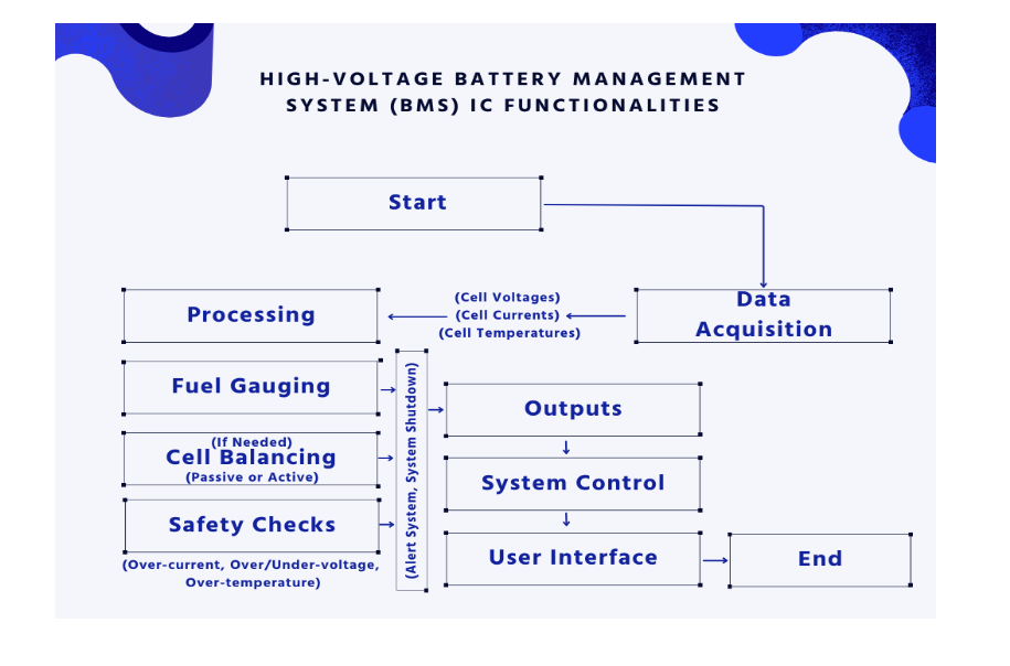
Data Acquisition
The BMS IC continuously monitors critical battery parameters like individual cell voltages, currents, and temperatures. This data is essential for:
- Identifying potential cell imbalances and triggering balancing actions.
- Detecting abnormal battery behavior like excessive temperature rise or over-current conditions.
- Providing system-level information for control algorithms and user interfaces.
High-voltage BMS ICs typically utilize high-resolution Analog-to-Digital Converters (ADCs) to measure cell voltages with high accuracy. Sampling rates for voltage and current measurements are crucial design considerations. A higher sampling rate provides more granular data but increases power consumption. The optimal sampling rate depends on the specific application and the need for real-time monitoring versus power efficiency.
Prioritizing Safety: Essential Protections for Your High-Voltage Batter Management System
In the high-voltage realm, safety is paramount. The chosen BMS IC should be equipped with robust protection features to safeguard the battery pack, the system itself, and ultimately, the user. Here are some key safety features to prioritize:
Over-current Protection (OCP)
This safeguards the battery and system from excessive current flow that can lead to overheating and potential damage. The BMS IC monitors current levels and triggers actions like cell balancing or system shutdown in case of over-current conditions.
OCP is typically implemented by setting a current threshold within the BMS IC. When the measured current exceeds this threshold, the IC can take various actions depending on the severity of the over-current event. These actions might include reducing the charging/discharging current, disconnecting the load, or issuing an alert to the system controller.
Over-temperature Protection (OTP)
High temperatures are detrimental to battery health and safety. The BMS IC continuously monitors battery pack temperature and triggers actions like reducing charging current or initiating cell balancing when temperatures exceed safe limits.
Many BMS ICs integrate temperature sensors or utilize communication with external temperature sensors to monitor battery temperature. The OTP feature works similarly to OCP, with pre-programmed temperature thresholds and corresponding actions to prevent thermal runaway within the battery pack.
Over-voltage Protection (OVP) and Under-voltage Protection (UVP)
These features shield the battery from damaging voltage extremes. OVP prevents excessive voltage during charging, while UVP safeguards against deep discharge that can permanently damage battery cells.
The BMS IC monitors the total battery pack voltage and individual cell voltages. When the voltage exceeds or falls below pre-defined thresholds, the IC can trigger actions like disconnecting the charger, reducing charging/discharging current, or issuing an alert.
Additional Safety Considerations
Some high-voltage BMS ICs offer advanced safety features to further enhance battery protection:
Cell Voltage Equalization
This feature actively equalizes cell voltages beyond passive balancing techniques, ensuring a more uniform voltage distribution and potentially extending battery life.
Safety State Machine
Sophisticated BMS ICs might implement a safety state machine that monitors various parameters and transitions the system into safe operating states based on pre-defined safety rules.
Example: The NXP Semiconductor MC33771 is a high-voltage BMS IC with integrated cell balancing, temperature monitoring, and a programmable safety state machine for comprehensive battery pack protection.
Communication is Key: Enabling Seamless System Integration
Modern BMS ICs go beyond standalone operation. They often integrate communication interfaces to seamlessly connect with other system components like the Motor Control Unit (MCU) or a Battery Management System (BMS) Supervisory Unit. Common communication protocols used in high-voltage BMS ICs include:
CAN bus (Controller Area Network):
This industry-standard protocol offers robust and reliable communication for real-time data exchange between the BMS IC and other system components. CAN bus enables features like:
- Transmission of cell voltage, current, and temperature data for system monitoring and control.
- Configuration of BMS IC parameters like cell balancing thresholds and safety settings.
- Receiving commands from the system controller for charging/discharging control.
SPI (Serial Peripheral Interface) and I2C (Inter-Integrated Circuit)
These protocols offer simpler communication options for smaller systems or for interfacing with specific components within the BMS itself.
The choice of communication protocol depends on factors like the complexity of the system, data transfer speed requirements, and compatibility with other system components. CAN bus is generally preferred for its robustness and ability to handle larger data packets in high-voltage systems, while SPI and I2C offer simpler implementations for specific communication needs within the BMS.
Practical Considerations: Thermal Management, Form Factor, and Beyond (continued)
Form Factor (continued)
The Texas Instruments INA3221, while a high-voltage (26V) current shunt monitor commonly used in conjunction with BMS ICs, exemplifies a smaller form factor option in a SOIC package. This is suitable for space-constrained designs.
Software and Development Tools
Simplifying development is key. Look for BMS ICs with readily available software and development tools. These tools can include:
- Configuration software for setting up cell balancing thresholds, safety parameters, and communication protocols.
- Evaluation kits to facilitate testing and verification of the BMS IC functionality within your specific system design.
- Application notes and reference designs to provide guidance on implementing the BMS IC and integrating it with other system components.
Example: The Analog Devices LTC6802 high-voltage battery monitor offers a comprehensive suite of development tools, including a graphical user interface (GUI) for configuration and an evaluation board for system prototyping.
Additional Considerations
While the core functionalities and safety features are paramount, some projects might require additional features to cater to specific needs:
Isolation
In some high-voltage systems, galvanic isolation between the BMS IC and other system components might be necessary for safety reasons. Look for BMS ICs with integrated isolation barriers to prevent leakage currents and potential safety hazards.
Example: The Linear Technology LTC6811 is a high-voltage battery monitor with integrated isolation, making it suitable for applications requiring galvanic isolation between the BMS and the system controller.
Redundancy: For mission-critical applications, redundancy in critical BMS functions might be a consideration. Some BMS ICs offer features like redundant cell voltage monitoring or communication interfaces to enhance system reliability.
Example: The TI bq76930 is a high-voltage battery gauge IC that features redundant cell voltage monitoring and multiple communication interfaces for increased system reliability.
Conclusion: Selecting the Perfect High-Voltage BMS IC – A Balancing Act
Choosing the right high-voltage BMS IC is a balancing act. It is about understanding your project’s specific needs for cell count, voltage range, and functionalities, while prioritizing safety features, communication capabilities, and practical considerations like thermal management and form factor.
By delving deeper into the technical specifications and functionalities of various BMS IC options, you will be well-equipped to make an informed decision. Do not hesitate to leverage the LiveBench Remote Lab to streamline development and ensure a successful integration of the BMS IC within your high-voltage system.
Ready to Put Your High-Voltage BMS Knowledge into Action?
This guide has equipped you with the knowledge to confidently navigate the world of high-voltage BMS IC selection. But theory is only half the battle. Now it is time to see these concepts in action!
Introducing LiveBench Lab’s High Voltage Battery Management System (US134):
Looking for a practical example of a high-voltage BMS solution? Look no further than LiveBench Lab’s US134. This development board serves as a proof-of-concept (POC) for a 28 cell battery management system, supporting a wide input range of 120V and output of 118V.
Here is how the US134 can help you take the next step:
- Validate your BMS design concepts: Test and experiment with real-world high-voltage battery management using a pre-built platform.
- Simplify development and integration: Leverage the US134 as a starting point, saving valuable time and resources during your BMS development process.
- Gain hands-on experience: The US134 provides a practical learning tool to solidify your understanding of high-voltage BMS functionalities.
Whether you are a seasoned system designer or just starting your high-voltage journey, LiveBench Lab’s US134 can be your valuable partner in innovation. Head over to their website to learn more and unlock the potential of your high-voltage battery project!