

The complexity of industrial control systems necessitates reliable and efficient power delivery solutions that maintain precise output performance under any conditions. This use case delves into the capabilities of Analog Devices’ LTM4653 Module regulator, a superior option for powering these critical systems. The LTM4653 offers exceptional features such as ultra-low noise emissions to meet EN55022 standards, a broad input and output voltage range, and adjustable switching frequency.
To thoroughly assess the regulator’s performance, a live hardware testing approach is proposed, encompassing operation mode analysis, regulation characteristics evaluation, transient response assessment, and boundary condition testing. Real-time data visualization enables users to scrutinize crucial parameters effectively.
Additionally, the integration of LiveBench, a cloud-based testing platform, allows instant access to real hardware labs worldwide, saving weeks and hours of evaluation effort, significantly reducing evaluation time and effort while facilitating streamlined testing procedures and in-depth exploration of the LTM4653’s behavior across diverse operating scenarios.
By combining live hardware testing with real-time data analysis and cloud-based platforms like LiveBench, engineers gain comprehensive insights into the LTM4653, aiding in the evaluation of robust, efficient, and compliant power delivery solutions for industrial control systems.
Challenge
Reduce Power Losses in Industrial Control with Efficient DC/DC Converters
Industrial control systems demand reliable and efficient power delivery for critical components, often in environments with strict EMI (Electromagnetic Interference) regulations. Traditional DC/DC converters can struggle to meet these stringent noise emission standards. The LTM4653 µModule regulator addresses this challenge with its ultralow noise design, compliance with EN55022 radiated emissions requirements, and broad input voltage range of 3.1V to 58V. LTM4653 ensures high accuracy and efficiency, making it an ideal solution for reducing power losses and meeting EMI standards in industrial control applications.
Solution
High-Efficiency Power Delivery for Industrial Control: The LTM4653 Module
Analog Devices’ LTM4653 uModule regulator offers a compelling solution for powering industrial control equipment. This ultra-low noise, 58V, 4A DC/DC step-down converter boasts exceptional features designed specifically for these demanding applications:
Precision power delivery solutions
The device features ±1.67% total DC output voltage error over line, load, and temperature variations, ensuring high accuracy. Integrated components and the need for only bulk input and output capacitors simplify design, making the LTM4653 ideal for reliable and efficient power delivery in industrial applications.
Wide Input and Output Voltage Range
The LTM4653 accommodates a broad input voltage range of 3.1V to 58V, making it suitable for various industrial power supplies. It also offers a flexible output voltage range, adjustable from 0.5V to 94% of the input voltage, ensuring compatibility with diverse control system components.
Configurable Switching Frequency
The switching frequency can be programmed within a range of 250kHz to 3MHz, allowing optimization for noise reduction or efficiency based on specific application needs.
Live Hardware Testing on LiveBench for power delivery solutions
Lab Capabilities:
- Conduct live testing of the LTM4653 uModule regulator on real hardware.
- Remote Accessibility:
- Conduct tests and evaluations from anywhere in the world via a secure internet connection.
- Access the board and testing equipment remotely through an intuitive web-based interface.
- Real-Time Data Monitoring:
- Observe and analyze real-time data from various test points, including input voltage, input current, output voltage, and output current.
- Receive instant feedback and updates during testing.
- High Precision Measurements:
- Conduct precise measurements using advanced equipment’s viz, Precision DC power supply, Tenma Electronic load, Data Acquisition System/Oscilloscope and sensors for special cases.
- Ensure accuracy and reliability of test results for any provided test to the fullest capability of device.
Measurement equipment’s the LiveBench consists of:
- Precision DC Power Supply: Provides stable and adjustable input voltages from 3.1V to 58V.
- Tenma Electronic Load: Simulates different load conditions for various tests.
- Data Acquisition System/Oscilloscope: Monitors switching frequency, waveform shapes, transient response, ripple, and noise, and records voltage and current over time.
- Sensors for Special Cases: External voltage/current measurement sensors
To showcase the LTM4653’s capabilities, a comprehensive live hardware testing setup is proposed, evaluating key performance parameters:
Measurement of parameters :
To showcase the LTM4653’s capabilities, a comprehensive live hardware testing setup is proposed, evaluating key performance parameters with wide range of tests performed on the device includes:
- Operation Mode
- Regulation Tests
- Performance Tests
- Efficiency Tests
Test to be performed on LiveBench and result observation:
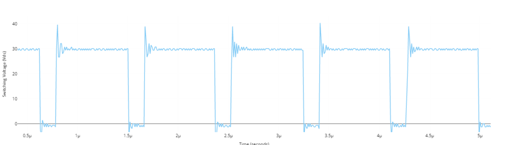
Operation Mode: Observe and analyze the switching waveforms to verify proper operation and switching behavior.
The converter is tested at 42V input voltage and 1A output current. One can measure and record switching voltage (Vds / Vce) simultaneously and the output response will be recorded and represented in the IU as output graph.
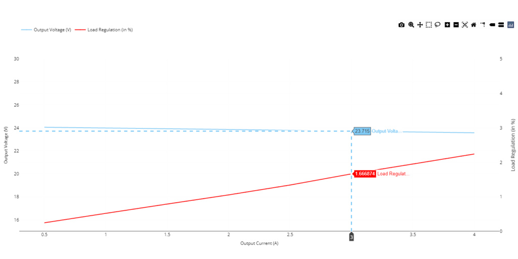
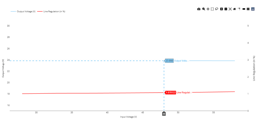
Regulation Tests: Measure and assess line and load regulation performance, ensuring stable output voltage even with fluctuations in input voltage or varying load currents.
Load regulation: Operating conditions are established for a 42V Input voltage, the load current is changed step by step. Every load current setting is used to measure the converter’s output voltage. To show the connection between the output voltage and the percentage regulation over the range of load currents, a graph is plotted.
Line regulation: Operating conditions are established for a 2A load current. Next, the input voltage is gradually adjusted while the output voltage is monitored. At each adjustment, the output voltage stability is observed and contrasted with the voltage without a load.
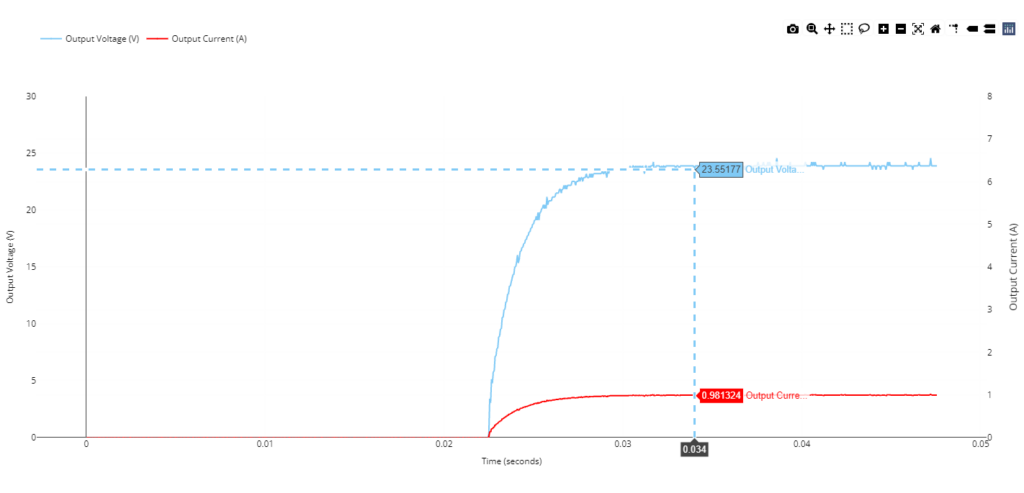
Performance Tests: Evaluate the regulator’s response to transient events, including startup and load transients. Additionally, measure and analyze efficiency across different operating conditions.
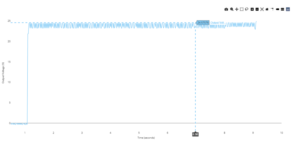
Startup transient response:
Operating conditions are established for 1A Load Current and 28V Input Voltage. Initializing the system to simulate the start-up phase is the first step in the testing process. The converter’s response is observed and documented, with particular attention paid to variables like output voltage stability, settling time, and over-shoot.
Load transient response: Operating conditions are established for a 28V Input voltage Rapid load variation in the converter replicate dynamic variations in power consumption during regular operation. Variations in the load are recorded and monitored through changes in the output voltage or current. The transient response of the converter is measured and documented, encompassing variables like ripple, overshoot, and settling time.
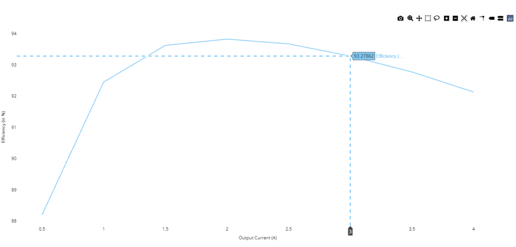
Efficiency: Operating conditions are established for a 42V Input voltage, The output current of the converter is systematically changed in steps during the testing process to simulate various load conditions. Concurrently, the converter’s corresponding efficiency is determined and documented for every load scenario. A graph of load current vs. efficiency curve is created by charting the relationship between load current and efficiency.
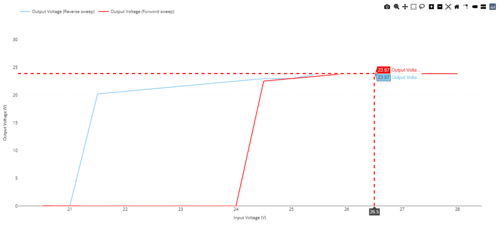
Boundary Conditions: Test the LTM4653 at the edges of its input voltage range to ensure proper functionality under extreme operating conditions.
Operating conditions are established for a 2A load current. In predetermined steps, the input voltage is systematically lowered from the rated voltage to the minimum input voltage. As the input voltage drops until it reaches the minimum input voltage, the output voltage variation is noted and observed. The input voltage is gradually raised back to the rated voltage after it has reached the minimum input voltage. As the input voltage is raised back to its rated level, the output voltage variation is once more noted and measured.
Benefits:
- Reduced Design Time: The LTM4653 Module minimizes design complexity with its compact form factor and integrated features.
- Reliable Power Delivery: Ensures stable and efficient power for sensitive industrial control equipment.
- Simplified Testing and Verification: Live hardware testing with real-time data visualization streamlines the evaluation process.
Conclusion
Enabling Reliable and Efficient Power delivery solutions for Industrial Control
The LTM4653 Module regulator by Analog Devices presents a compelling solution for powering industrial control equipment, offering a unique combination of low noise performance, wide voltage range, and ease of use.
By combining comprehensive hardware testing with the advanced features of LiveBench, engineers gain a deeper understanding of the LTM4653’s performance across various operating conditions, including its robustness under extreme circumstances. This empowers them to design reliable and efficient power management solutions for demanding industrial control applications.