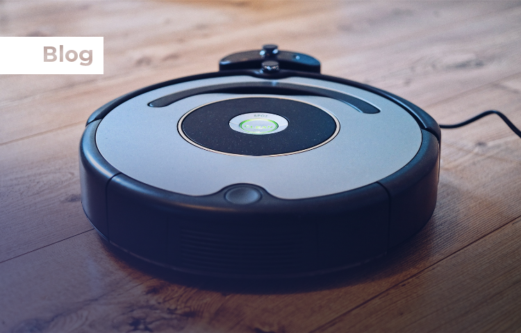
The robotic vacuum cleaner market has experienced remarkable growth, reaching $11.14 billion in 2025 with projections to hit $35.56 billion by 2035. This represents a 12.3% CAGR, driven by consumer demand for automated cleaning solutions and technological advances in AI-powered navigation systems. For system design engineers, this growth presents both opportunities and complex technical challenges in developing efficient, intelligent cleaning robots.
Advanced Navigation Systems: Beyond Basic Obstacle Avoidance
Modern robotic vacuums have evolved from primitive “bump-and-go” systems to sophisticated autonomous navigation platforms. Simultaneous Localization and Mapping (SLAM) technology has become the cornerstone of effective navigation, enabling robots to build real-time environmental maps while tracking their precise position.
LiDAR-Based Navigation Systems
LiDAR SLAM provides the highest accuracy for robotic vacuum navigation. Modern systems operate at 5-10Hz scanning frequencies, delivering 360-degree environmental awareness with millimeter precision and obstacle detection ranges up to 6 meters. Implementation of low-cost MEMS LiDAR sensors can reduce navigation errors by 40% and optimize cleaning routes to cut total cleaning time by 20%.
Key technical specifications for LiDAR integration:
Scanning Rate: 4000 scans per second for comprehensive mapping
Angular Resolution: Sub-degree precision for detailed obstacle mapping
Range Accuracy: ±3cm typical for furniture and wall detection
Power Consumption: <2W average during operation
Visual SLAM Implementation
Camera-based Visual SLAM (VSLAM) offers cost-effective navigation with advanced object recognition capabilities. VSLAM systems excel at detecting small objects like cables and pet toys that LiDAR might miss. Modern implementations use algorithms like ORB-SLAM for feature detection and tracking.
Challenges and Solutions:
Low-light performance: Mitigated by fusing IMU data for stability on textured surfaces like rugs
Motion blur: Advanced algorithms compensate for rapid robot movement
Computational requirements: Optimized for embedded ARM processors with dedicated vision processing units
Multi-Modal Sensor Fusion
The most robust navigation systems combine multiple sensor modalities. LiDAR-camera fusion systems like CamVox demonstrate reliable performance by using ORB-SLAM 2.0 with Livox LiDAR sensors and RGB-D cameras. IMU integration provides motion correction and handles temporary sensor failures.
Precision Motor Control: Optimizing Efficiency and Performance
BLDC Motor Advantages in Robotic Vacuums
Brushless DC (BLDC) motors have become the standard for high-performance robotic vacuums due to their superior efficiency and control characteristics. BLDC motors achieve >85% energy conversion efficiency compared to 75% for traditional brushed motors, directly translating to extended battery life and more powerful suction.
Technical Benefits:
High-speed operation: Easily exceed 100,000 RPM for centrifugal suction fans
Linear speed-torque characteristics: Enable precise speed control across variable loads
Low acoustic noise: Electronic commutation eliminates brush friction noise
Extended lifespan: No mechanical brush wear extends operational life by 50-100%
Multi-Motor System Architecture
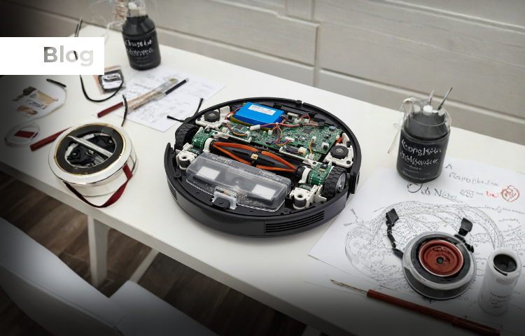
Robotic vacuums typically employ 3-4 separate BLDC motors:
Wheel Drive Motors (Dual 6-12V):
Differential steering control via independent speed regulation
Encoder feedback for precise odometry and navigation
Torque limiting to prevent stalls on thick carpets or obstacles
Current draw: 2-4A continuous, 8A peak during high-load conditions
Brush Motors:
Trapezoidal commutation for high torque at low speeds (200-800 RPM)
Adaptive speed control based on surface type detection
Debris detection via current monitoring to prevent hair tangling
Suction Fan Motors:
High-RPM operation: 20,000-35,000 RPM for centrifugal airflow
Variable speed control: 30-100% duty cycle based on cleaning mode
Airflow generation: Up to 100 CFM (cubic feet per minute)
Advanced Motor Control Techniques
Field-Oriented Control (FOC) and sinusoidal commutation significantly improve performance:
Noise reduction: 15-20dB lower acoustic emission compared to basic six-step commutation
Efficiency improvement: 5-10% higher efficiency across variable load conditions
Vibration minimization: Smoother torque delivery reduces mechanical stress
Comprehensive Sensing Architecture
Hall Effect Sensor Integration
Hall effect sensors provide critical feedback for both motor control and system monitoring in robotic vacuums. These magnetic sensors offer contactless operation, immune to dust contamination that affects optical encoders.
Motor Commutation Applications:
Three-phase BLDC control: Three Hall latches per motor provide 120° electrical angle feedback
Incremental encoding: Dual Hall sensors with magnetic disk provide speed and direction feedback
Back-EMF sensing: Eliminates need for Hall sensors in sensorless control modes
System Monitoring Applications:
Dustbin detection: Hall switch with magnet ensures proper dustbin installation
Wheel drop sensing: Detects when robot is lifted off ground via spring-loaded Hall switches
Bump detection: Linear Hall sensors with magnet-embedded bumpers provide gentle collision feedback
Technical Specifications:
Power consumption: <5µA quiescent current for battery life optimization
Operating temperature: -40°C to +125°C for reliable operation
Response time: <1µs for high-speed motor commutation
Magnetic sensitivity: 30-60 Gauss switching points for reliable detection
Multi-Modal Environmental Sensing
Cliff Detection Systems:
IR emitters/receivers: Detect height changes >25mm to prevent falls
Ultrasonic rangefinders: Proximity detection for gentle approach to obstacles
Duty cycling: 500ms polling intervals reduce average power consumption by 30%
Contact and Proximity Sensors:
Flexible bumper strips: Convert mechanical impacts to voltage changes
Capacitive sensors: Detect nearby objects before physical contact
Acoustic sensors: Monitor motor load and debris detection through sound analysis
Battery Life Optimization Strategies
Modern robotic vacuums target 90-120 minutes runtime from 2600-5200mAh Li-ion battery packs. Achieving this requires comprehensive power management across all subsystems.
Quiescent Current Management
System-level power optimization:
Ultra-low power ICs: <50µA sleep modes for MCU and sensor controllers
Sensor duty cycling: Reduce continuous monitoring to essential functions only
Dynamic voltage scaling: 3.3V for logic circuits, 12V only during motor bursts
Expected improvement: 20-25 minutes additional runtime through optimized power management
Motor Efficiency Optimization
Load-adaptive control strategies:
Efficiency mapping: Operate brushes at 70% duty cycle during light loads
Surface detection: Automatically adjust suction power based on floor type
Predictive scheduling: Reduce motor speeds in low-traffic areas
Back-EMF sensing: Eliminate Hall sensor power overhead in sensorless modes
Battery Capacity Scaling:
Entry-level: 2600mAh, 90-minute runtime for apartments <1000 sq ft
Mid-range: 3200-4000mAh, 120-150 minute runtime for homes up to 2000 sq ft
Premium: 5200-6400mAh, 200+ minute runtime for large homes >2500 sq ft
Allegro A89301 Advanced Features
The Allegro A89301 represents current state-of-the-art in integrated BLDC motor control for robotic applications:
Technical Specifications:
Voltage range: 5.5-50V operation accommodates various battery configurations
Current capability: 11A continuous, 15A peak without external cooling
Control modes: Sensorless FOC with automatic startup and fault protection
Interface options: I2C, analog, PWM, and clock-based speed control
QuietMotion technology: Proprietary algorithms reduce EMI and acoustic noise
Robotic Vacuum Optimizations:
Ultra-quiet operation: <40dB acoustic emission during normal operation
Soft-start control: Gradual acceleration prevents dust clouds and mechanical stress
Adaptive commutation: Automatically adjusts to motor parameters without tuning
Fault protection: Overcurrent, overvoltage, and thermal shutdown with automatic recovery
Motor Drive Controller Selection: A89301 and Competitive Analysis
| Specification | Allegro A89301 | Microchip ATA6847 | TI MCF8329A |
| Part Number | A89301 | ATA6847 | MCF8329A |
| Manufacturer | Allegro MicroSystems | Microchip Technology Inc. | Texas Instruments |
| Positioning | Integrated sensorless FOC motor controller + gate driver | Three-phase BLDC pre-driver SBC (needs external MCU + MOSFETs) | Integrated sensorless FOC motor controller + gate driver |
| Supply Voltage Range (V) | 5.5 – 50 | 3 – 42 (motor supply VDH: 4.9 – 32) | 4.5 – 60 |
| Continuous Current (A) | 11 (integrated capability) | External FET-dependent (supports up to ~100 nC charge per MOSFET) | External FET-dependent (driver supports up to ~2 A gate drive) |
| Peak Current (A) | 15 | Gate drive peak supports high-side/low-side MOSFETs (configurable) | Gate drive peak ~1 A source / 2 A sink |
| Control Mode | Code-free sensorless FOC, closed-loop speed optional | External MCU control, SPI configuration, supports 6-step & FOC | Code-free sensorless FOC, closed-loop speed / power / current |
| Gate Drivers | Integrated 3 high-side + 3 low-side | Gate driver for 6 external NMOS (3 half-bridges) | Integrated 3 high-side + 3 low-side external MOSFET drivers |
| Communication Interface | I2C, Analog, PWM, Clock | SPI, digital PWM inputs, watchdog, interrupt pins | I2C, Analog, PWM, Frequency, DAC monitoring |
| Special Features | QuietMotion, Soft-On/Off, Windmill start, Short-circuit protection | Integrated 5V/3.3V LDOs, CS amplifiers, B-EMF detection, watchdog | EEPROM config, flux weakening, MTPA, spread spectrum EMI, diagnostics |
| Key Advantages | Ultra-quiet, simple design, wide voltage range | Flexible MCU-based control, ISO 26262/SIL2 safety ready | High integration, standalone operation, advanced FOC tuning |
| Target Applications | Premium fans, pumps, small appliances, compact motors, Robotic Vacuums | Home appliances, power tools, drones | Cordless vacuums, garden tools, appliances, BLDC/PMSM modules |
| Operating Temperature (°C) | –40 to +105 | –40 to +150 | –40 to +125 |
| Package Type | QFN-24 (4 × 4 mm) | VQFN-40 (5 × 5 mm) | VQFN-36 (5 × 4 mm) |
| Acoustic Performance | < 40 dB acoustic emission | Depends on MCU algorithm, slew-rate controlled gate drive | Improved via auto dead-time comp. + spread spectrum EMI |
| Fault Protection | OCP, UVLO, thermal shutdown, lock detection | OCP, VDS short detection, UVLO, watchdog, limp-home | OCP, UVLO, motor lock detect, thermal shutdown, fault pin / I2C |
| Relative Cost | Baseline (100%) | ~120% of A89301 (safety certified SBC) | ~110% of A89301 |
| BOM Impact | Standard complexity (external FETs integrated) | Higher (needs external MCU + FETs + passives, but has regulators) | Lower (standalone operation with EEPROM reduces external parts) |
| Market Segment | Consumer appliances, premium BLDC drives | Automotive + industrial BLDC (tools, appliances, drones) | Cost/performance optimized appliances and cordless tools |
System Integration and Validation
Sensor-Motor Integration Benefits
Unified control architecture combining Hall sensors with advanced motor drivers creates synergistic performance improvements:
Performance Enhancements:
Closed-loop odometry: Hall encoder feedback enables precise navigation without external sensors
Real-time load monitoring: Current sensing detects surface transitions and debris accumulation
Predictive maintenance: Motor parameter monitoring predicts bearing wear and brush replacement needs
Design Simplification:
Shared power rails: Reduce conversion losses by 3-5%
Common communication bus: I2C interface supports both sensors and motor controllers
Reduced BOM complexity: Integrated solutions cut component count by 20-25%
Accelerated Development and Testing
Modern development approaches emphasize rapid prototyping and remote validation:
Hardware-in-the-Loop Testing:
Remote laboratory access: Cloud-based testing platforms enable global collaboration
Real-time data logging: Continuous monitoring of motor efficiency, thermal performance, and acoustic signatures
Automated test sequences: Scripted validation reduces development cycle time by 40-60%
Performance Validation Metrics:
Current injection testing: Up to 50A load simulation for motor characterization
Thermal monitoring: Real-time temperature mapping during extended operation
Acoustic analysis: Sound pressure level measurement across frequency spectrum
The convergence of advanced navigation algorithms, efficient motor control, and intelligent sensing systems is defining the next generation of robotic vacuum cleaners. System engineers who master the integration of these technologies—from SLAM-based navigation to FOC motor control to multi-modal sensing—will create products that deliver superior cleaning performance while meeting stringent requirements for battery life, acoustic performance, and user experience.
Success in this rapidly growing market requires balancing technical excellence with cost optimization, leveraging integrated solutions where appropriate, and maintaining focus on the core user requirements of effective cleaning, quiet operation, and reliable autonomous function. The technical foundation established today will determine competitive positioning as the market continues its aggressive growth trajectory toward $35 billion by 2035.
Elevate Your Robotic Vacuum Designs with TenXer Labs
From navigation smarts to efficient control, these elements shape the next generation of vacuum cleaner robots. Join our webinar on October 9, 2025, at 8:30 PM IST for a deep dive, featuring a live A89301 demo and insights from Allegro’s Neil Gokhale and TenXer’s Bhavana M R.


