What is a Buck Regulator?
A buck regulator, also known as a buck converter, is a type of DC-DC converter that steps down a higher input voltage to a lower output voltage while maintaining efficient power transfer. By using a combination of switching elements and passive components, buck regulators are able to deliver high efficiency, which is crucial for modern electronic devices. They operate by switching a transistor (usually a MOSFET) on and off rapidly, and filtering the resulting pulses to create a lower, stable output voltage.
The efficiency and simplicity of the buck regulator make it an essential tool in applications requiring voltage step-down, from industrial electronics to consumer gadgets. Unlike linear regulators that dissipate excess energy as heat, buck regulators use pulse-width modulation (PWM) to control energy flow, minimizing energy loss. This is why they are found in applications where power efficiency is critical, such as battery-powered devices and power management ICs.
Historical Background
The buck converter concept dates back to the early 20th century, with the modern implementation taking shape in the 1960s when advances in semiconductors, such as diodes and transistors, allowed for more efficient and compact designs. Companies like Texas Instruments and Motorola were pioneers in the development of these switching regulators as the demand for compact, energy-efficient power supplies grew, particularly with the rise of portable electronics.
Components of a Buck Regulator
A buck regulator consists of several key components that work together to step down a higher input voltage to a lower output voltage efficiently. Each component plays a specific role in the regulation and stability of the voltage conversion process. Let’s explore these components in detail:
1. Switching Transfer (MOSFET)
The switching transistor, typically a MOSFET (Metal-Oxide-Semiconductor Field-Effect Transistor), is the primary component that controls the on/off states of the regulator. It rapidly switches the input voltage on and off at a high frequency, allowing the conversion from high to low voltage.

- Function: The MOSFET alternates between conducting and blocking the current. During the “on” phase, it allows current to flow to the inductor, while during the “off” phase, it blocks the current, allowing energy stored in the inductor to power the load.
2. Inductor
The inductor is a coil that stores energy in the form of a magnetic field when current flows through it. It smooths the transitions between the “on” and “off” states of the MOSFET, ensuring a steady flow of current to the load.
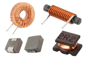
- Function: The inductor helps maintain continuous current flow by storing energy when the MOSFET is on and releasing it when the MOSFET is off. It plays a critical role in reducing voltage ripple and stabilizing the output.
3. Diode
In a basic buck regulator, a diode is used to provide a path for current when the switching transistor (MOSFET) is off. It allows the current from the inductor to continue flowing to the load, ensuring smooth output.

- Function: The diode acts as a freewheeling diode, directing the current during the MOSFET’s “off” cycle. In synchronous buck regulators, the diode is often replaced by another MOSFET for greater efficiency.

4. Output Capacitor
The output capacitor is used to filter and smooth out the output voltage by reducing the voltage ripple caused by the switching action of the MOSFET. It ensures that the output voltage remains as steady as possible.

- Function: It stores electrical charge and releases it as needed to smooth voltage fluctuations. A well-sized output capacitor helps minimize ripple and noise, making the output voltage stable for sensitive components.
5. Control Circuitry (PWM Controller)
The control circuitry in a buck regulator manages the operation of the switching MOSFET. It uses feedback from the output to adjust the duty cycle, ensuring that the output voltage remains constant despite variations in load or input voltage.
- Function: The control circuit, often based on pulse width modulation (PWM), adjusts the on and off time of the MOSFET to maintain the desired output voltage. It constantly monitors the output and makes adjustments to keep the voltage within target levels.
6. Feedback Loop
The feedback loop monitors the output voltage and feeds the information back to the control circuitry. This feedback allows the regulator to adjust the duty cycle to compensate for changes in load or input voltage, ensuring stable output.
- Function: The feedback loop helps the regulator maintain accuracy. It compares the output voltage with a reference voltage and makes adjustments to the switching action to stabilize the output.
7. Input Capacitor
The input capacitor helps to reduce noise and stabilize the input voltage by filtering out high-frequency spikes or transients. This ensures the input voltage supplied to the MOSFET is clean and free from fluctuations.
- Function: It prevents sudden voltage spikes and reduces electromagnetic interference (EMI) by smoothing the input power before it reaches the switching transistor. A stable input helps the regulator perform more efficiently.
These components work together to convert the input voltage to a lower output voltage with high efficiency, making buck regulators ideal for various applications where efficiency, size, and power dissipation are critical factors.
Key Features of Buck Regulators
1. High Efficiency
Buck regulators are renowned for their high efficiency, often exceeding 90%. This efficiency is achieved through the regulator’s ability to convert excess voltage into useful output rather than dissipating it as heat, which is common in linear regulators. In a linear regulator, excess voltage is simply burned off, wasting power and generating heat. On the other hand, buck regulators transfer power through a switching mechanism, minimizing energy loss and heat generation.
This high efficiency is particularly valuable in battery-powered devices like smartphones, laptops, and wearables, where energy savings directly extend battery life. For example, stepping down from 12V to 5V using a linear regulator can waste over 50% of the energy, whereas a buck converter can do the same with only 5-10% energy loss. In high-power applications like server farms, this efficiency reduces the need for extensive cooling solutions and prolongs component life by lowering heat stress.
2. High Switching Frequency
Buck regulators operate at high switching frequencies, often ranging from hundreds of kilohertz (kHz) to several megahertz (MHz). The benefit of high switching frequencies is that they allow the use of smaller passive components, such as inductors and capacitors. Smaller components contribute to more compact circuit designs, which is highly desirable in modern electronics like smartphones, tablets, and wearable devices where space is limited.
While higher switching frequencies reduce the size of these components, they also lead to increased switching losses. Therefore, engineers must find a balance between frequency and efficiency depending on the application requirements. A high frequency can make designs more compact but requires careful consideration to avoid unnecessary efficiency loss.
3. Wide Input Voltage Range
Buck regulators are versatile and can handle a wide input voltage range, often from 3V to 40V, making them adaptable to various power supply configurations. This flexibility is crucial in applications such as automotive or industrial systems, where input voltages can vary significantly. For instance, a buck regulator can step down from high supply voltages like 24V to lower voltages (e.g., 3.3V or 5V) required by the load.
In automotive systems, where battery voltages fluctuate due to engine starts or varying loads, this wide input range ensures the buck regulator can maintain a stable output voltage. The ability to work with varying input levels increases the regulator’s versatility and reduces the need for different designs for each system.
4. Continuous and Discontinuous Modes
Buck regulators can operate in continuous conduction mode (CCM) or discontinuous conduction mode (DCM), depending on the load current. In continuous mode, the current through the inductor never falls to zero, which results in smoother operation and lower output ripple. This mode is more common under heavier loads. Discontinuous mode occurs under lighter loads, where the inductor current drops to zero during part of the switching cycle, improving efficiency but potentially increasing output ripple.

Switching between these two modes allows the regulator to optimize performance under varying load conditions. At light loads, discontinuous mode reduces switching losses and improves efficiency, while at heavier loads, continuous mode maintains steady, low-ripple output. Modern regulators often switch between these modes automatically, ensuring the best balance of efficiency and performance.
5. Synchronous vs. Non-Synchronous Design
A synchronous buck regulator replaces the traditional diode with a MOSFET, which is actively controlled to reduce power loss. This improvement is particularly important in low-voltage applications, where even a small voltage drop across a diode can significantly reduce efficiency. In a typical diode, there’s a 0.7V drop, which can have a notable impact when the output voltage is low, such as 1.8V or 1.2V.

Synchronous buck regulators minimize these losses by using a MOSFET instead of a diode, resulting in a 2-5% efficiency improvement in many cases. This design is especially beneficial in applications where power efficiency is critical, such as processors and other electronics that operate on tight power budgets.
6. Low Output Voltage Ripple
Buck regulators are designed to minimize output voltage ripple, the small residual AC voltage present on the DC output. Ripple can cause issues in sensitive circuits, leading to errors or noise in analog and digital systems. Buck regulators achieve low ripple through the use of output capacitors and precise control of the switching cycle.

Low ripple is particularly important in devices such as audio equipment, precision analog circuits, and communication systems where signal integrity is crucial. Microcontrollers and RF circuits, for instance, may malfunction or suffer performance degradation if exposed to high ripple, making ripple suppression an essential aspect of buck regulator design.
Applications of Buck Regulators
A buck regulator, also known as a step-down converter, is a highly efficient dc-dc converter designed to step down a higher input voltage to a lower output voltage. Its applications span across industries, thanks to its versatility, high performance, and ability to optimize power conversion in various systems.
1. Battery Chargers and Portable Devices
Buck regulators are widely used in battery chargers to convert a wide input voltage range into a suitable battery voltage for efficient charging. Their ability to handle high efficiency and reduced power losses ensures longer battery life for portable devices. By reducing voltage ripple and optimizing the switching frequency, buck regulators maintain a consistent output voltage to protect sensitive components.
2. Automotive Systems
In automotive systems, buck regulators play a critical role in providing stable power for various electronic subsystems. These regulators operate effectively across a wide input voltage range supplied by a car’s alternator or battery, delivering high reliability under dynamic conditions. The synchronous buck converter is particularly popular in automotive designs for its reduced conduction losses and superior converter efficiency.
3. Modern Microprocessors
Buck regulators are essential in powering modern microprocessors, which require stable and low supply voltage levels for optimal performance. Using a buck converter circuit, the input voltage source is stepped down to meet the precise reference voltage needs of processors, minimizing output voltage ripple for stable operation.
4. Powering DC Motors and Energy Storage Systems
Buck regulators are ideal for powering DC motors and managing energy storage elements. In these applications, the inductor voltage plays a significant role in ensuring efficient energy transfer during the switching period. By reducing power consumption, they maximize stored energy efficiency and extend operational life.
5. Power Supply for Sensitive Electronics
Buck regulators are commonly used in power supply designs for sensitive electronics, ensuring a steady state output voltage with minimal fluctuations. Components like the output capacitor, inductor value, and capacitor selection are critical to achieving low output voltage ripple and stable output current, even under variable load current conditions.
6. Renewable Energy Systems
In renewable energy systems, such as solar power setups, buck regulators are employed in maximum power point tracking (MPPT). By stepping down the higher voltage from solar panels to a desired output voltage, they ensure efficient energy utilization while maintaining high converter efficiency.
7. Industrial and Automotive Systems
The robustness of buck converters makes them indispensable in automotive systems and industrial applications. For instance, in automotive systems, high side switch and low side switch configurations are used to regulate power for engine control units, infotainment systems, and safety sensors.
Operating Principles in Applications
The core operating principle of a buck regulator involves alternating energy storage and release through an inductor, controlled by two power switches—typically a high side switch and a low side switch. During the switching period, inductor current is regulated to achieve the desired output voltage, minimizing voltage drop and ensuring consistent current flow.
Control circuitry dynamically adjusts the duty cycle to regulate the output voltage.
The simplified schematic of a buck regulator demonstrates how inductor current and parasitic resistance impact performance.
Synchronous buck converters leverage advanced circuit designs to further reduce switching losses and improve efficiency.
Advantages of Buck Regulators
High efficiency for both input and output power conversion.
Reduced power losses through optimized circuit topology.
Compatibility with a wide input voltage range, making them ideal for diverse power environments.
Enhanced battery life in portable and automotive systems.
Reliable performance under high current demands, including average inductor current and load current scenarios.
Key Design Considerations
Inductor value and capacitor selection are critical in minimizing voltage ripple and maintaining stable output current.
Switching frequency directly impacts efficiency, with higher frequencies reducing output voltage ripple but increasing switching losses.
Designs must account for ohm’s law to minimize conduction losses caused by parasitic resistance.
Incorporating a freewheeling diode reduces inductor falls and stabilizes inductor current during operation.
Application in Circuit Topologies
Buck regulators are integral to various circuit topology designs, including:
Linear regulators: Although less efficient, they are sometimes paired with buck regulators for precise voltage drop control.
Synchronous buck designs for minimizing power losses and optimizing current flow in high-performance systems.
Buck regulators are indispensable in modern electronics, offering a blend of high efficiency, low cost, and reliable performance. Their applications range from powering portable devices and automotive systems to ensuring precise power delivery in modern microprocessors and battery chargers. As advancements in circuit topology and power devices continue, buck regulators remain a cornerstone of efficient power conversion in diverse industries.
Key Physical Characteristics of Buck Regulators
1. Inductor Size
The inductor in a buck regulator plays a crucial role in energy storage and filtering. Larger inductors provide better filtering and lower current ripple, resulting in more stable output voltages, especially in continuous conduction mode. However, they also take up more space and can introduce higher losses due to parasitic resistances. In portable devices where space is limited, smaller inductors are preferred despite their tendency to increase ripple currents. Designers must balance the size of the inductor with performance, considering that higher switching frequencies enable the use of smaller inductors but may lead to greater switching losses.
2. Capacitor Size and Type
The output capacitor smooths voltage ripple and ensures stable DC output. Larger capacitors generally offer better filtering but take up more space, while smaller ones may allow more ripple at the output. Capacitors with low equivalent series resistance (ESR), such as ceramic capacitors, are commonly used in modern buck regulators to reduce ripple. However, these capacitors can be sensitive to temperature and may offer lower capacitance at higher voltages, so choosing the right type of capacitor is critical to achieving optimal performance.
3. Switching Frequency
The switching frequency refers to how quickly the switching element (e.g., MOSFET) turns on and off. Higher switching frequencies reduce the required size of inductors and capacitors, which is advantageous in space-constrained designs. However, higher frequencies can also increase switching losses and electromagnetic interference (EMI), potentially reducing overall efficiency. Designers must carefully select the optimal switching frequency, balancing size, efficiency, and potential EMI issues, especially in compact applications like smartphones or tablets.
4. Output Voltage Ripple
Output voltage ripple is the small fluctuation in the output voltage caused by the switching action of the regulator. The size of the inductor, capacitor ESR, and switching frequency all affect the magnitude of this ripple. Low output voltage ripple is particularly important in sensitive circuits like microcontrollers, sensors, and RF communication devices, where excessive ripple can introduce noise, affect signal integrity, or even cause malfunctions. Engineers must prioritize ripple suppression in precision systems to ensure stable and reliable performance.
5. Power Dissipation and Thermal Management
Power dissipation in a buck regulator mainly occurs in the switching element (e.g., MOSFET) and the inductor, which generate heat during operation. As load current increases, so does the amount of heat produced. Effective thermal management—using heat sinks, thermal vias, or spreader plates—is essential to prevent overheating, which can degrade performance or damage components. In compact systems, thermal design must balance heat dissipation with efficiency, as seen in devices like laptops and smartphones, which integrate advanced thermal management features to ensure reliable operation under high power conditions.
6. Control Method (PWM vs. PFM)
Buck regulators use either pulse-width modulation (PWM) or pulse-frequency modulation (PFM) as their control method. PWM operates at a fixed switching frequency and varies the on-time of the switching element to regulate output voltage, offering smooth output but lower efficiency at light loads. PFM adjusts the switching frequency based on load demand, improving efficiency under light loads by reducing switching losses, though it can increase ripple and EMI. Choosing between PWM and PFM depends on the application—PFM is ideal for devices with varying loads, while PWM suits applications with constant load conditions needing stable output.
Importance of Evaluating Buck Regulators
Evaluating a buck regulator is essential to ensure that it performs well in real-world applications, meeting the required efficiency, stability, and reliability. Buck regulators are widely used in devices ranging from smartphones to industrial systems, and their performance directly impacts the power delivery to sensitive electronic components. Thorough evaluation ensures that the buck regulator can handle varying conditions, such as fluctuating power supplies, sudden changes in load, or environmental challenges like heat, without compromising on efficiency or output stability.
By evaluating these regulators, engineers can identify potential issues, optimize designs, and ensure the product meets performance goals. Key parameters play a major role in understanding how well the regulator will perform in different scenarios. Here’s a breakdown of these important parameters.
Key Parameters for Evaluating Buck Regulators
1. Input Voltage Range
The input voltage range indicates the range of voltages the regulator can handle from the power source. For instance, in applications like automotive systems, where the power supply can vary (such as battery voltage fluctuating when a car engine is turned on or off), the regulator must be able to manage these changes without malfunctioning. By evaluating the input voltage range, engineers ensure the regulator can consistently deliver stable power even when the input voltage shifts.
2. Output Voltage
The output voltage is the final voltage delivered to the connected load. A stable and accurate output is critical in ensuring that the electronic components or circuits relying on it function correctly. If the output voltage fluctuates too much, it can affect the performance of devices such as processors, sensors, or communication modules. Evaluation helps ensure that the regulator provides a stable voltage, especially when the load changes or the input voltage varies.
3. Efficiency
Efficiency measures how well the buck regulator converts input power to output power without wasting energy. Since any energy lost is dissipated as heat, low efficiency can lead to overheating and unnecessary energy consumption. This is especially important in battery-powered devices, where energy efficiency translates into longer battery life. Evaluating the efficiency ensures that the regulator delivers power without excessive losses, making it ideal for applications like smartphones or portable devices where power saving is crucial.
4. Load Regulation
Load regulation refers to the regulator’s ability to maintain a steady output voltage as the current drawn by the load changes. For instance, in devices like processors or motors, the demand for power can shift suddenly as the device goes through different states of activity. A regulator with good load regulation keeps the voltage stable, even when these changes occur. Evaluating load regulation ensures that the system continues to function correctly under varying operating conditions.
5. Line Regulation
Line regulation examines how stable the output voltage remains when the input voltage fluctuates. If the power supply feeding the regulator is inconsistent, like in industrial applications or vehicles, good line regulation ensures that the output voltage stays constant, preventing damage or malfunctions in connected devices.
6. Switching Frequency
The switching frequency is the rate at which the buck regulator turns the internal switches (typically MOSFETs) on and off to convert voltage. A higher switching frequency allows for smaller components like inductors and capacitors but can result in greater energy loss as heat. Conversely, lower frequencies reduce heat but require larger components. Evaluating the switching frequency helps designers balance between efficiency, space, and heat management, especially in compact designs like wearable devices or consumer electronics.
7. Output Ripple and Noise
Output ripple refers to small, unintended voltage fluctuations at the output caused by the switching action of the regulator. Noise refers to high-frequency variations that could interfere with sensitive electronics. Minimizing ripple and noise is essential for precision devices like sensors or communication systems. By evaluating this parameter, engineers ensure that the power supply remains clean and stable, which is vital for avoiding interference or errors in connected circuits.
8. Transient Response
Transient response evaluates how well the buck regulator handles sudden changes in load demand, such as when a processor shifts from idle to active mode, causing a sudden increase in current. A good transient response ensures that the output voltage remains stable during these transitions, preventing dips or spikes that could disrupt the system. Evaluating this response is crucial for ensuring reliability in systems that experience frequent load changes.
9. Thermal Performance
Thermal performance focuses on how the buck regulator manages heat generated during operation. In high-power or compact applications, overheating can lead to system failure or reduced lifespan of components. Proper thermal management ensures the regulator stays within safe temperature limits. Evaluating thermal performance helps designers implement appropriate cooling solutions, such as heat sinks or optimized layouts, to prevent overheating.
10. Protection Features
Modern buck regulators often include protection features like overcurrent protection (OCP), overvoltage protection (OVP), and thermal shutdown to safeguard the circuit in case of faults. For instance, if too much current flows through the regulator, the overcurrent protection will limit the current to prevent damage. Evaluating these features ensures the regulator can protect both itself and the connected devices from potential issues, making the system more robust and reliable.
11. Quiescent Current
Quiescent current is the amount of current the regulator consumes when it is not supplying any load (i.e., in standby or idle mode). In battery-powered devices, it’s important to keep this current as low as possible to extend battery life. Evaluating the quiescent current ensures that the regulator doesn’t unnecessarily drain power when the device is in low-power or sleep mode.
12. Electromagnetic Interference (EMI)
Because buck regulators operate using high-frequency switching, they can generate electromagnetic interference (EMI), which could affect other nearby electronic devices. Evaluating EMI helps designers minimize interference, ensuring compliance with regulatory standards and preventing issues in sensitive applications like medical equipment or communication systems.
References :
- https://en.wikipedia.org/wiki/Buck_converter
- https://www.st.com/en/power-management/buck-regulators.html
- https://www.ti.com/lit/an/slvaed3a/slvaed3a.pdf?ts=1728888661340&ref_url=https%253A%252F%252Fwww.google.com%252F
- Buck converter design by Jens Ejury : a997c023d0eda74b0a3c42d4b38ca9c.pdf (badcaps-static.com)
- https://www.nwengineeringllc.com/article/dc-dc-converter-inductor-selection-guidelines-for-high-power-systems.php