
An evaluation kit makes it easy to improve the process of assessing a device’s design and functionalities, and lets you to understand how the device works and performs.
Often, the evaluation kit is designed for the purposes of engineering development, demonstration, and evaluation. It is particularly useful for system designers who need to characterize new products within laboratory settings.
In a traditional sense, the evaluation kit is best described as any electronic component of a semiconductor system, a comprehensive starter package meticulously curated to expedite the process of assessing designs intended for automotive, industrial, video, and communications applications.
A perfect example of the evaluation kit is a pre-assembled circuit board housing a highly sensitive sensor and a differential amplifier circuit. In addition, it incorporates plated-through holes for wire connections or a specialized header designed explicitly for the purpose of facilitating experimentation and testing of novel semiconductor products.
Another example of an evaluation kit comprises a preassembled and thoroughly tested PCB, a set of essential cables, a power adapter, an LED panel, and an SD card.

Semiconductor manufacturers and distributors use several terms interchangeably to refer to evaluation kit, including “development kit,” “starter kit”, ”Eval Kit”, “EVK” and occasionally, simply “EV kit”. The term “demonstrative board” is just another word for the evaluation kit, sparsely used to describe the same tools for product assessment and testing by system engineers.
The Evaluation Kit allows you to produce a proof of concept to speed up the path to deployment ensuring it aligns with your customers’ requirements and preferences.
System designers identify these quick-start kits as a cost-effective solution for showcasing the feasibility of market-ready solutions. Through rigorous device testing and debug, it becomes possible to thoroughly perform electronic design validation and functionalities of these devices and subsequently analyze the outcomes. A robust analytical method for refining the solutions which paves the way for their large-scale deployment in the market.
This kit offers the essential building blocks required for the development, prototyping, and deployment of applications. Engineers can use it to create a working proof of concept for their device deployment.
When system designers are ready to begin evaluating or developing their devices, they can choose from a wide range of kits. These kits are designed with feature sets and form factors to expedite the designers’ projects.
The contents and packaging of the evaluation kit may vary based on customer orders. Here are the most used basic components of an evaluation kit:
The majority of current sensor evaluation kit – hold a great promise for use in lab settings – affixed to PCB boards to showcase the sensor’s functionality. In some EVKs, a comprehensive assortment of PCBs and sensors is employed, primarily to accommodate the various mechanical orientations required for facilitating customer testing and part filtering.
Several notable examples of EV kits that have been developed are available, For example, EV kit incorporates a custom-designed PCB with traces running beneath the sensor elements. With this configuration, system designers can quickly test the sensor of real-world applications. Customers have the flexibility to experiment with different current levels to observe and analyze the sensor’s output.
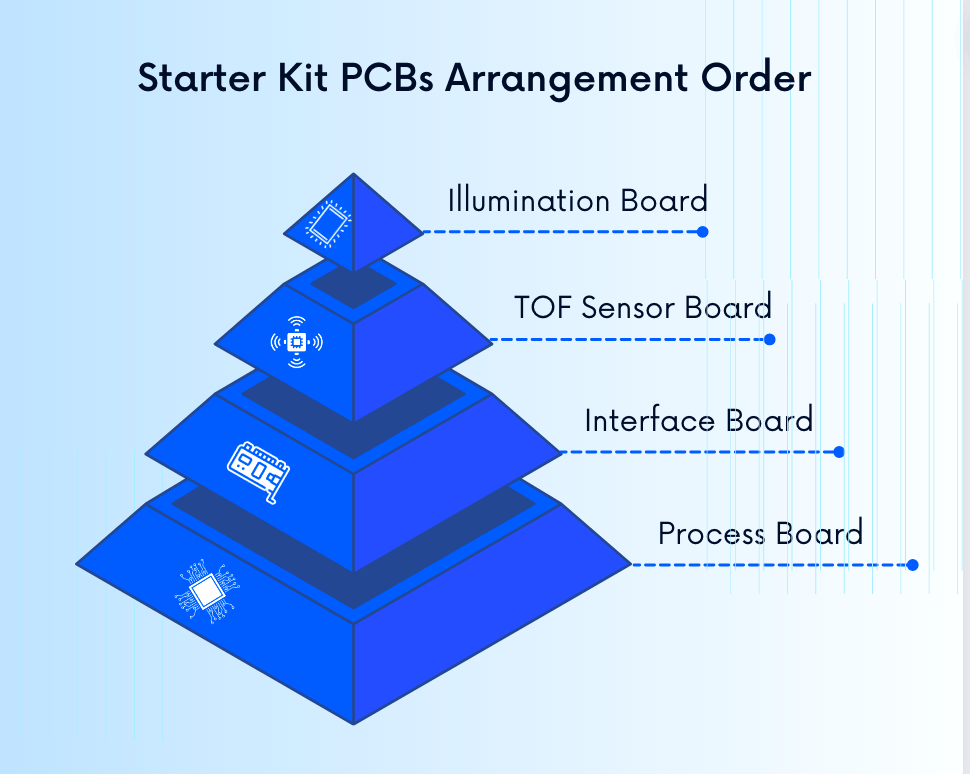
The starter kit comprises stacked PCBs arranged in the following order from top to bottom: illumination board, TOF sensor board, interface board, and processor board.
Many evaluation kit designs make use of FPGAs for high-speed data processing and signal processing tasks.
The Evaluation Kit includes two communication ports: one USB port and one CAN interface.
The Evaluation Kit serves as an FPGA platform tailored for the development of cost-optimized FPGA designs. It supercharges in feature integration, offering the industry’s state-of-art combination of low power consumption, high reliability, and advanced security.
This evaluation kit simplifies the development of FPGA designs centered around transceiver I/O, enabling the creation of PCI Express and Gigabit Ethernet-based systems with ease. Plus, the board follows the small form-factor PCIe standard, easing rapid prototyping and evaluation on any desktop PC or laptop equipped with a PCIe slot.
The kit also includes end-to-end EVM Kit hardware development that assists with different stages of creating electronic systems: hardware design, schematics, and board layout.
This hardware development applies to EVMs (Evaluation Modules) designed for a wide range of components including Data Converters, Sensors, Power Management ICs, Amplifiers, RFICs, power filter, EMI filter and more.
a. USB Cable:
It facilitates communication between the PC application and the drive PCB, is included in the compartment located underneath the evaluation kit PCB.
b. USB IN Port
It is provided to connect the PCB to a PC using the supplied USB cable. This connection enables the device control software to communicate with the PCB. Additionally, there is a solder bridge on the underside of the board. When this bridge is connected, it allows the evaluation system to be powered directly from USB IN, eliminating the need for the mains power adapter.
c. POWER IN
It refers to the connection point for the mains transformer, which provides power to the entire system.
d. Battery:
To initiate the charging process, the designer should first connect the mains power supply after attaching the battery and selecting the battery power source.
e. Mains Power Supply
It is responsible for converting AC (alternating current) to DC (direct current) for the motherboard. Generally, a region-specific adapter will have already been installed for your convenience.
f. Green LED:
It is used to indicate whether the pump is in the on or off state.
g. Jumpers
It enable the module to be disconnected from components that are not needed, such as the USB interface.
h. Firmware:
Depending on the specific protocol you are targeting, it’s essential to load different firmware releases onto the host Flash memory. System designers should verify the availability of the required software releases by contacting their local manufacturer’s sales office.
i. Graphical User Interface ( GUI )
The intuitive GUIs designed for the Windows software environment connects users to seamlessly upgrade the firmware release and configure and control the evaluation kit.
As a part of firmware update, it improves various microcontroller platforms, a pack of different ARM controllers, microcontrollers like the MSP430, TIVA, I.MX series, Stellaris, Sitara, PIC, and more. Additionally, it is compatible with DSPs.
IC Evaluation Kit frequently incorporate firmware, which may reside on the Motherboards or ‘dongles’ for connection to individual DUT (Device Under Test) evaluation boards. Alternatively, the firmware can be integrated directly into the DUT Evaluation Boards.
j. Pin Headers:
You can conveniently probe any crucial signals needed for development at the pin headers.
The natural flexibility of the evaluation kit enables designers to gain the essential system knowledge and product experience needed for their specific applications.
k. Magnet:
Magnets play a pivotal function in these kits, as they are combined with circuit boards for securing various components. Plus, many kits are furnished with ZIF (Zero Insertion Force) sockets as part of the package.
The core component of most kits features a magnetic switch powered by a lithium coin cell. These magnetic switches are seamlessly integrated with sensor elements and are supported by digital signal processing electronics to boost their capabilities for better functionality.
Some kits even include a miniature bar magnet, allowing system designers to gain a better understanding of how these sensors operate. These magnets are optimized for detecting specific ranges of amps.
Manufacturers opt for ultralow-power magnetic switches, under certain conditions, which are conveniently integrated into a demo board. Worthy of mention is the magnets are not restricted only to switches and miniature applications; they are also used in high-speed magnetometers, specially designed for precise amp detection.
Plus, certain kits may include split-pole magnets and plastic magnets to aid in locating fixtures and enhance the versatility of the kit’s components.

The provided example designs are intended to expedite the prototyping process for high-performance computing and networking systems in various markets. No matter your application, kickstart your design process with user-friendly starter tools. These tools not only shorten design cycles but also enhance the overall product experience. They provide direct access to all registers through the manufacturer’s proprietary software, empowering system designers to create their own firmware with ease.
The majority of evaluation boards and breakout boards come with open-source hardware designs, which also apply to the interface. System designers can easily download these files for a fast-track design implementation, enabling them to have their prototype rapidly deployable.
The Evaluation Board speeds up the development process for customers by assisting product testing, ultimately evaluate them to accelerate their overall development timeline.
Apart from being directly mounted on the Evaluation Board, these devices can also be connected remotely to the Evaluation Board using wire leads. This flexibility enables testing in challenging environments or within prototype products for proof-of-concept trials of the customer’s final product.
Traditionally, testing with a standard kit could take up to a week, but thanks to advancements in certain platforms, it can now be accomplished in just an hour. The testing can be conducted under actual operating conditions and offers users several benefits, including the measurement of switching loss, the selection from a variety of gate driver options to align with specific requirements, and the optimization of switching behavior.
The evaluation kit and accompanying software simplify the evaluate process and demonstrating sensors. This eliminates the necessity for customers to write any code before obtaining sensor measurements.
Developing a solution through programming is a labor-intensive and time-consuming process, with each step demanding substantial effort. However, these kits deliver a streamlined alternative. Instead of programming the devices from scratch, they allow users to configure the settings and actions of the devices, substantially simplify the process.
Debugger – Programming and debugging (target) through the JTAG/SWD port
GUI: The graphical user interface simplifies the programming process and includes readily available code libraries for greater convenience in usage. The graphical user interface offers rapid setup, supports direct mode commands, visualizes real-time behavior through graphs, and logs and stores data. Moreover, all settings can be easily exported for use in your own firmware project.
The kit includes a user-friendly graphical user interface that is both free and easy to use, making it ideal for the development of stand-alone applications. The integrated development environment is adaptable to different use of commands utilization in direct mode. It also allows real-time behavior monitoring with graphical visualization, and enables data logging and storage.
It provides insights to understand the technology capabilities of devices, allowing customers to make more informed decisions about components quickly. As a result, system designers can have no-code adoption while evaluating the device for reduced price.
The kit also features a rapid evaluation process that incorporates:
a) Evaluation board design,
b) Firmware, which can be implemented on microcontrollers (uC), Field-Programmable Gate Arrays (FPGA), or Digital Signal Processors (DSPs) and
c) Graphical User Interfaces (GUIs) to facilitate customer evaluation of a wide range of devices.
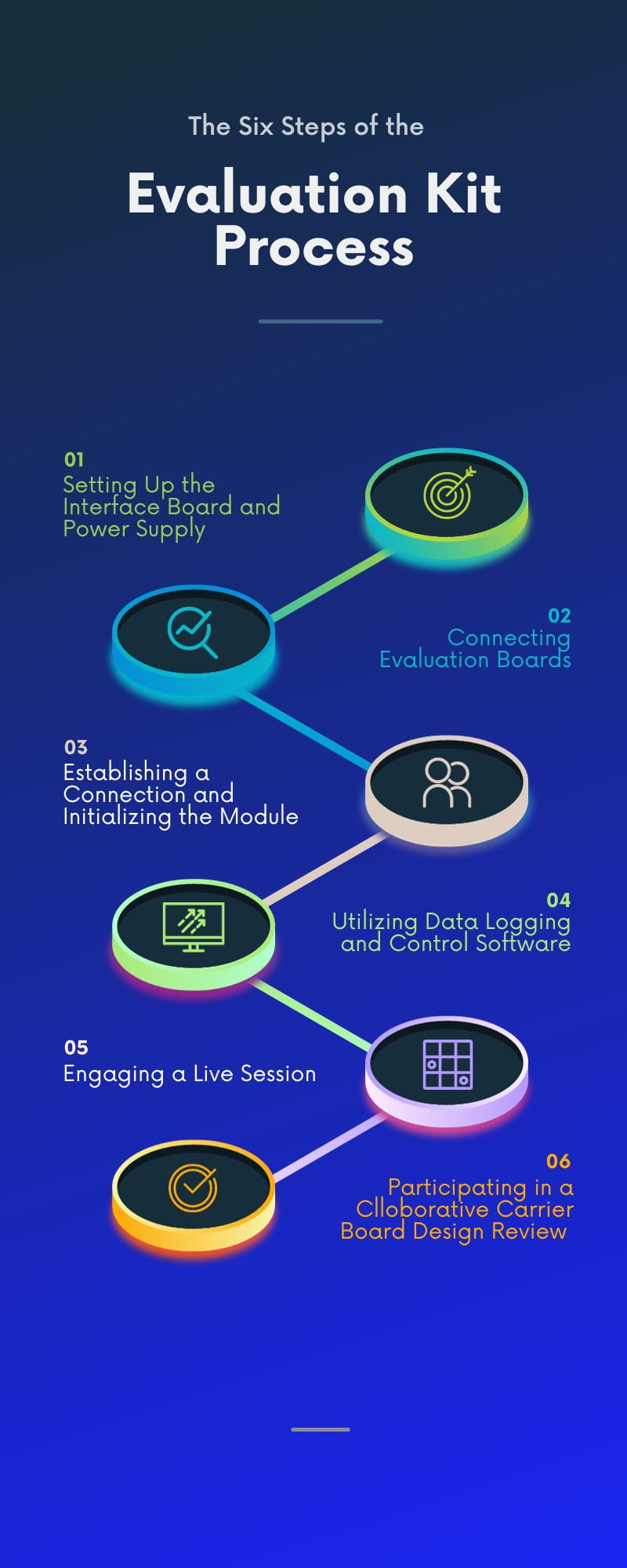
Here is the quick start guide of the EV Kit process to initiate quick and effortless testing of devices:
Depending on the chosen kit, the interface board serves as the bridge between the PC and the manufacturer’s powerful ICs. Begin by attaching the universal power supply, then connect it to a PC USB port, and finally, plug in one or two systems.
It offers a quick and straightforward start, allowing you to set your device in motion within minutes. It provides complete access to all registers, full functionality, and diagnostic capabilities.
In certain manual books, the initial step is explicitly outlined as follows: Begin by configuring the jumpers to activate the evaluation boards. Next, connect the power jack or an external power supply to the EV board. This is essential to ensure a stable VCC, which is necessary to provide the module with its required static and peak current consumption.
Connect system designers’ preferred evaluation board to the interface board using the connector board. It’s even possible to link multiple evaluation boards together.
Install the provided free software and unlock the full potential of the solutions. For diagnostic purposes, all signals are accessible using probes on the bridge board. To streamline the transition to the processor such as Arm Cortex® core , the board can be disconnected.
Utilize a USB cable to establish a connection between the evaluation board and your PC. This step is crucial as it aids in the detection and installation of a COM port on your PC.
You can identify the assigned COM port name, such as “COM12” in Windows systems in Linux systems, by checking the device manager (for Windows) or the respective system directory (for Linux).
Next, run a terminal program, such as hterm for Windows, and open the COM port using the default settings of the mounted radio module.
To ensure a clean start-up of the module, press the reset button after the module has been powered through the USB jack or an alternative power system.
The data logging and control software simplifies the evaluation of various sensor performances and facilitates the seamless capture of performance data results.
Engage in a live session, typically lasting for 4 hours, with the manufacturer’s technical team. During this session, you will:
After you’ve prepared your board schematics, we offer a carrier board design review. In this collaborative review, we will examine your design together and provide you with an initial Device Tree Structure example tailored to your design.
Typically, an evaluation kit encompasses a preassembled circuit board equipped with components such as a high-sensitivity sensor and a differential amplifier circuit. Additionally, it features output (OUT) plated-through holes that facilitate easy wire connections.
These include an assembled and tested PCB, necessary cables, a power adapter, an LED panel, and an SD card. The EV kit typically comprises an assortment of key components, including a circuit board, sensors, a magnetic switch, User LEDs, amplifier signal processing integrated circuits (ICs), and a battery-powered demonstrator.
Many companies create EV kits featuring a pre assembled circuit board complete with a sensor and amplifier circuit. These kits are designed with a user-friendly “plug and play” concept, allowing designers to easily connect the power supply. This streamlined setup enables immediate testing without the need for any complex configuration or setup procedures.
However, common components, such as software and firmware, are typically included as part of the package.
The components included in the evaluation kit offer a valuable head start in the development of your products. This Evaluation Kit (EVK) streamlines evaluate and debug process of developing intelligent products using the manufacturer’s System on Modules (SoMs). It encompasses hardware, an SDK, source code examples, and development support.
The EVK is designed to support all of the manufacturer’s SoMs, regardless of their form factor, and offers a wide array of easily accessible connectors to access all of the SoM’s functionality.
Smaller kits can be tailored to align with your specific requirements and budget constraints. Additionally, certain kits are available at significantly reduced prices and are specifically crafted for evaluation centers, providing individuals with a hands-on opportunity to thoroughly debug the product.
The primary objective of this Evaluation Kit is to empower users to perform a rapid and comprehensive evaluation of the aesthetics, tactile characteristics, and overall functionality of the respective devices or systems under consideration.
The evaluation kit is designed to facilitate the rapid and straightforward evaluation of modules and resources. It is an ideal tool for constructing a functional proof of concept for your device concept.
In essence, an evaluation kit serves as an essential tool for semiconductor professionals to assess and validate the performance of semiconductor devices and systems during the product development phase.